TEA-MO

Our project after the chariot design focused on some sort of need people needed. We each came up with 5 ideas for everyday solutions. Our top contenders, after consolidation, were an automatic tea steeper, a automatic trumpet tuner, and an ink dispensing device for dry erase markers. After reviewing again, we decided to use either the tea steeper, or the trumpet tuner.
Our next task was to create some actual size model for these ideas to demonstrate their functionality, effectiveness, etc. Basically see if the product is viable for both the world and for a good learning experience.


We received some feedback from our instructor, Professor Spenko, who brought up some valid concerns. Starting with the trumpet tuner, the device seemed a little to simple to make. This was because it was mainly motor that was connected to a feed screw. Another reason was because the design seemed bulky from the perspective of a trumpet player. The desired weight for that device was about 500 grams. When held at the end of the trumpet, this will cause a torque, that will cause discomfort in using the trumpet/tuner combo.
The tea maker seemed like more of a challenge. The idea was that a diffuser, attached to the cap of the tea steeper, would be in contact with the water. The diffusion holes would lines up and the tea flavor would be free to roam across the water. When the steep time was over, the holes would misalign, causing the flavor to stop diffusing. The point of this was to stop bitter flavor from spreading when the optimal steep time is surpassed. We attempted to produce some simple calculations for the torque required within the device.
The tea maker seemed like more of a challenge. The idea was that a diffuser, attached to the cap of the tea steeper, would be in contact with the water. The diffusion holes would lines up and the tea flavor would be free to roam across the water. When the steep time was over, the holes would misalign, causing the flavor to stop diffusing. The point of this was to stop bitter flavor from spreading when the optimal steep time is surpassed. We attempted to produce some simple calculations for the torque required within the device.

As a result of these calculations, we were able to find that lowest rated servo that could handle the torque requirements. A 9V battery was selected for the power source, a micro controller, and Bluetooth sensor were purchased. The micro controller simply told the servo what to do. The 9V powered all devices and circuitry. The Bluetooth sensor would allow us to set the steeping time, and temperature based on the type of tea we wish to use, straight from our smart phones.
Our critical function was that the diffuser aligned and misaligned when needed with the diffuser housing, in order to allow and stop tea flavor from spreading.
Our critical function was that the diffuser aligned and misaligned when needed with the diffuser housing, in order to allow and stop tea flavor from spreading.
A practical model was made from PVC to test out this critical function. A cut away section was used in order for interested viewers in our device to be able to see at the rotating mechanism.


The problem with this was that water still leaked in between the drivetrain (or in between the gears). After trying many different possible solutions, (plumbing tape, plumbing lubricant, O-rings, V-rings), we decided to go back to an idea that was mentioned long before this was made. The idea was magnetic drive train. Simply use attracting magnets to rotate the diffuser from a sealed off compartment.

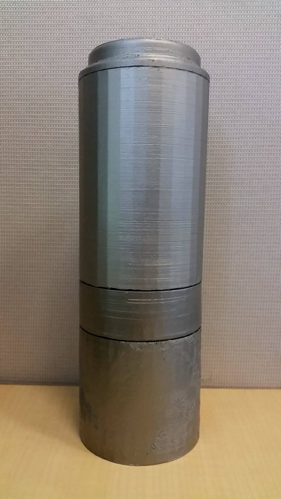
This stopped any water from getting into the electronics (in theory). Our parts were 3D printed, meaning that in no way were the walls waterproof. Water leaked through the pores and flaws of the plastic. We tried food safe silicon coatings, but the dimensions were then thrown off with the addition of material, meaning that the components could not come together. However, the rotating mechanism still worked, and parts were painted Stainless Steel color to make it look futuristic.


The problem with this was that water still leaked in between the drivetrain (or in between the gears). After trying many different possible solutions, (plumbing tape, plumbing lubricant, O-rings, V-rings), we decided to go back to an idea that was mentioned long before this was made. The idea was magnetic drive train. Simply use attracting magnets to rotate the diffuser from a sealed off compartment.

This stopped any water from getting into the electronics (in theory). Our parts were 3D printed, meaning that in no way were the walls waterproof. Water leaked through the pores and flaws of the plastic. We tried food safe silicon coatings, but the dimensions were then thrown off with the addition of material, meaning that the components could not come together. However, the rotating mechanism still worked, and parts were painted Stainless Steel color to make it look futuristic.